What are RSS Walls?
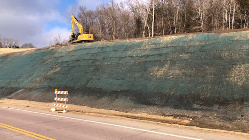
A reinforced soil slope is defined as a compacted fill embankment that incorporates geosynthetic reinforcement to increase the soil shear to enhance the stability of the embankment when site conditions require an embankment with a steeper angle of repose (how steep soil can naturally be piled relative to a horizontal plane) or if the embankment is intended to carry a load considered unstable with the existing subgrade.
There are two primary considerations when designing a reinforced slope:
- Internal stability
- External stability
A Reinforced soil slope often includes erosion control measures or facia treatment to protect against surface failures (external stability) in addition to the internal failures that are addressed with geosynthetic reinforcement (internal stability).
Secondary Geogrid
When building a reinforced slope, we will primarily depend on a secondary reinforcement with a light to moderate geosynthetic fabric or grid in tight vertical spacing with relatively short embedment lengths (how far horizontally into the slope these extend). These layers will provide superficial stability to protect the embankment from shallow plane failure at the surface, while also giving compaction equipment a good platform in which to compact soil lifts all the way to the face of the slope. These layers will either be wrapped around the face of the slope and folded back on top of the compacted lift in order to encapsulate the embankment soil, or they will terminate at the slope face and be finished with an appropriate rolled erosion control product. There are also circumstances in which both techniques are used, and the slope is hydroseeded, to ensure the best vegetation possible. Vegetation is the most effective protection against soil erosion, so this will always be a key factor in designing a permanent slope.
Primary Geogrid
The main method of reinforcement for our will be our primary geogrid, these layers will typically be higher strength geosynthetic products with much longer embedment lengths that are placed in less frequent layers than secondary reinforcement. These layers will address our internal stability.
Surface Treatments
Surface treatments are typically designed around the finished slope steepness. In slopes of 45 degrees or less, it will typically be advantageous to use a rolled erosion control product to retain soil and prevent soil erosion, while establishing and reinforcing permanent vegetation.
However, when slopes exceed 45 degrees in relativity to a horizontal plane, it’s often best to use wire forms that are either lined with geosynthetic or high performance rolled erosion control product that can retain fine soils while establishing vegetation through the facia treatment. Wire forms do not offer structural strength and should not be considered a structural element. They are placed only to keep the embankment at the desired batter (slope angle) during construction, and to assist the facia treatment in retaining soil. These can be left exposed, or they can be covered
Installation Instructions
This is a very basic description of the construction technique and a full sequencing should be provided by a geotechnical engineer along with construction drawings prior to installation.
Step 1 – Subgrade Preparation
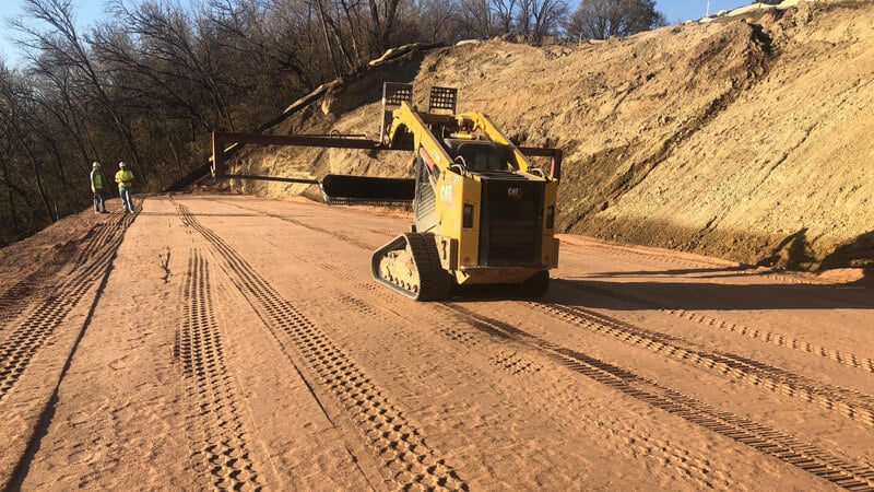
Remove unsatisfactory material and debris. Excavate or fill and compact suitable bedding material to desired elevations in a stepped fashion according to the elevation of individual soil lifts as determined by construction drawings.
Step 2 – Reinforcement Placement
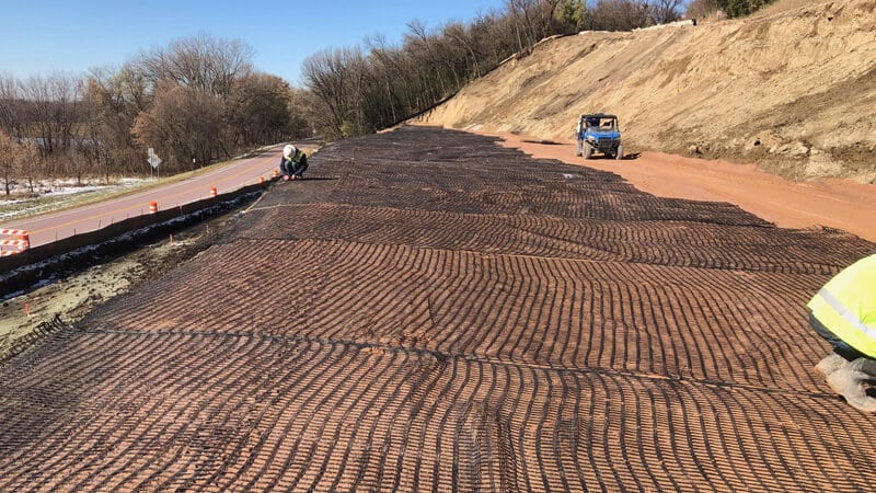
Place reinforcement as determined by construction drawings to match embedment, elevation, and orientation as determined by the design engineer. Ensure geosynthetic reinforcement is free of wrinkles and folds and is pulled taught by using soil staples or pins. Splicing in the direction parallel to the face of the slope is prohibited.
Step 3 – Fill Placement
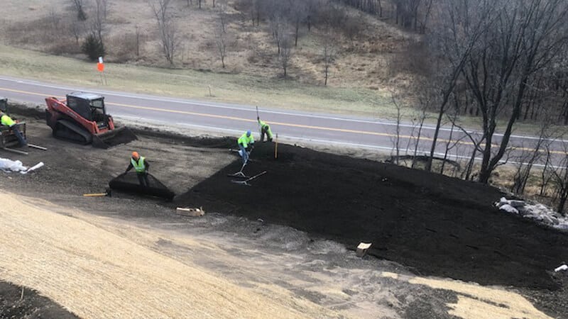
Place reinforcement beginning at the face of the slope and moving toward the end of the fabric or grid to ensure geosynthetic is pulled taught being careful to prevent wrinkles, folds, or tears. If wire baskets are used, they will also be placed at the indicated location prior to fill placement, leaving enough geosynthetic to wrap the face and make the next geosynthetic embedment length on the subsequent lift. If geosynthetic is to terminate at the face of the slope, you will line the wire form with indicated facia treatment prior to fill, being sure to cut around struts to allow the fascia to lay in full contact of the wire form.
A minimum of 6 inches of soil is required prior to the operation of vehicles on the geosynthetic. Avoid sudden stopping or braking, and do not turn tracked equipment on the fill area to avoid displacement. Light rubber tire vehicle operation can sometimes be acceptable if it is infrequent and slow, and turning is minimized.
Ensure fill is compacted as indicated in construction drawings before placing the next layer of reinforcement, wire forms, and fill.
Step 4 – Slope Finishing / Erosion Control
When all soil lifts and geosynthetic have been placed according to construction drawings, finish slope with either a soil treatment and final erosion control blanket, or by establishing vegetation through the facia treatment and wire baskets as indicated by an engineer.
Want more information?
We would love to help answer any additional questions you have about specifications or applications. Contact us below or view our Geogrid products.
